1. OVS Offload#
1.1. Introduction#
Open vSwitch(OVS) is often used in conjunction with companion applications to enhance and extend its capabilities. OVS offload is a companion application which enhance OVS functionality between host ports and mac ports.
Existing Marvell SOC’s lacks direct communication channel between Host PEM and MAC, hence dedicated ARM cores are required to intercept packets from Host and relay them to MAC ports, and reciprocally manage the packet flow between the two.
OVS-offload is a DPDK graph based application intended for bridging the void between Host PEM (SDP, virtio) and Ethernet MAC (RPM).
1.2. Architecture#
OVS harnesses DPDK port representors to seamlessly integrate with hardware-accelerated interfaces, optimizing packet processing path and enhancing network performance.
Traffic steering rules typically necessitate preliminary software processing. OVS must handle traffic among various device endpoints prior to their linkage. This process is streamlined by ‘port representors’, functioning as a frontend interface for OVS.
VM1 and VMn, depicted here, are two virtual machines operating on the x86 host, with Octeon connected as a PCI endpoint to the host. OVS utilizes VF representors VF1 and VFn to facilitate switching between these VMs. These representors initially receive traffic from their respective VMs. After OVS classifies this traffic, flow rules are offloaded to the hardware, enabling direct, high-speed network connectivity between the two VMs without additional traffic being directed to OVS.
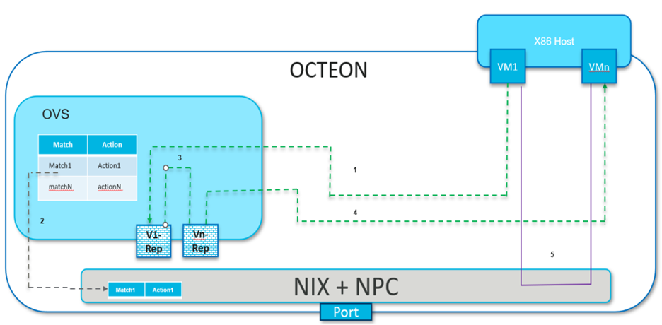
Following are steps to demonstrate packet flow:
1. Initial VM1 traffic, failing to find a matching hardware flow entry, is redirected to OVS via representor port VF1.
OVS categorizes the packets and readies the flow rules for hardware offloading.
The packets are then routed to VMn via its representor port VFn by OVS.
VMn receives the initial traffic from VM1 via OVS.
5. Post offloading of the rules to the hardware by OVS, all traffic between VM1 and VMn occurs directly, bypassing OVS.
1.2.1. Packet Flow - Wire-VM Communication and vice versa#
The diagram below illustrates the process of VM1, hosted on a local machine, establishing communication with a peer machine across the network. To ping VM1, the peer machine initiates the process by sending out the first ARP request to retrieve VM1’s MAC address.
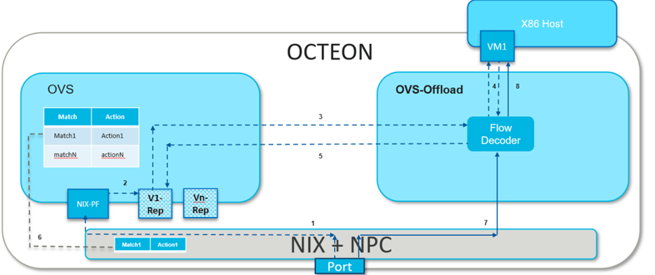
1. Within the Octeon, in the absence of a direct flow rule for routing the packet to VM1, the packet is guided towards its PF, which is typically bound to OVS in most cases.
2. Upon receiving the ARP packet, OVS, functioning as a switch, broadcasts it to all its ports that are part of the bridge, which includes the PF port. At this point OVS also associates the MAC address of peer machine with PF port as part of MAC learning.
3. The ARP request is received by all VMs represented through representor ports on the OVS bridge. However, only the intended recipient of this packet responds with an ARP reply.
4. The ARP reply from VM1 is channeled to OVS through its representor port. Given that the ARP reply’s destination MAC address matches that of the peer machine, OVS forward it via the PF port.
5. OVS offloads the flow associated with the ARP response, aiming to enable subsequent ARP packets to reach VM1 directly.
6. Subsequently, peer machine sends ICMP packets which also reaches VM1 via representors due to missing flow rule related to ICMP packets.
7. OVS also offloads the ICMP-related flow rules to the hardware, ensuring that all future ICMP packets can reach VM1 directly from the network.
1.3. Getting the sources and compile#
OVS-offload application is part of the DAO package and follow
steps to build DAO
1.4. Setting up the Environment#
Before launching ovs-offload, OVS should be running with the required port
representors.
Note
Follow the steps to get started with OVS with port representors
For ovs-offload solution each port representor represents a SDP port and RPM port as a pair and each SDP port is mapped to a unique RPM port. Hence for 3 interfaces on host side - requires 3 SDP VF and 3 RPM VFs bind to ovs-offload application and 3 port representors are bind to an OVS bridge providing switching between them.
1.4.1. Binding required devices#
ovs-offload app needs a ESW VF device to communicate with OVS for exception path, equal no of SDP VFs and RPM (NIX) VFs to form a pair.
1.4.1.1. Binding ESW VF#
ESW PF is bind to OVS while ESW VF is bind to ovs-offload app to enable data path between each other.
Create VF, check for device ID 0xa0e1 viz ESW VF and bind to vfio-pci
# echo 1 > echo 1 > /sys/bus/pci/devices/0002\:1c\:00.0/sriov_numvfs

# lspci | grep a0e1
0002:1c:00.1 Ethernet controller: Cavium, Inc. Device a0e1 (rev 50)

# dpdk-devbind.py -b vfio-pci 0002:1c:00.1
1.4.1.2. Binding SDP and RPM VFs#
Note
SDP PF doesn’t participate in datapath while NIX PF in common scenarios is bind to OVS
Check for device ID 0xa0f7 viz SDP VF and bind to vfio-pci
# dpdk-devbind.py -s
0002:1f:00.1 'Octeon Tx2 SDP Virtual Function a0f7' if=sdp31-0 drv=rvu_nicvf unused=vfio-pci
0002:1f:00.2 'Octeon Tx2 SDP Virtual Function a0f7' if=sdp31-1 drv=rvu_nicvf unused=vfio-pci

# dpdk-devbind.py -b vfio-pci 0002:1f:00.1
# dpdk-devbind.py -b vfio-pci 0002:1f:00.2
Create VFs, check for device ID 0xa064 viz RPM (NIX) VF and bind to vfio-pci
# echo 2 > /sys/bus/pci/devices/0002\:02\:00.0/sriov_numvfs

# dpdk-devbind.py -s
0002:02:00.1 'Octeon Tx2 RVU Virtual Function a064' if=eth1 drv=rvu_nicvf unused=vfio-pci
0002:02:00.2 'Octeon Tx2 RVU Virtual Function a064' if=eth5 drv=rvu_nicvf unused=vfio-pci

# dpdk-devbind.py -b vfio-pci 0002:02:00.1
# dpdk-devbind.py -b vfio-pci 0002:02:00.2
1.5. Launching the application#
dao-ovs-offload [EAL options] -- -p PORTMASK
                                 --portmap(PCI_BDF1, PCI_BDF2)[,(PCI_BDF3, PCI_BDF4)]
                                 --config(port,queue,lcore)[,(port,queue,lcore)]
                                 [--max-pkt-len PKTLEN]
                                 [--pcap-enable]
                                 [--pcap-num-cap]
                                 [--pcap-file-name]
                                 [--enable-graph-stats]
Where,
* -p PORTMASK: Hexadecimal bitmask of ports to configure
--portmap:Between which 2 PCI ports forwarding shall be enabled. In most common case 1 of the PCI BDF is SDP VF and other is RPM VF.--config (port,queue,lcore)[,(port,queue,lcore)]:Determines which queues from which ports are mapped to which cores.--max-pkt-len:Optional, maximum packet length in decimal (64-9600).--pcap-enable:Optional, Enables packet capture in pcap format on each node with mbuf and node metadata.--pcap-num-cap:Optional, Number of packets to be captured per core.--pcap-file-name:Optional, Pcap filename to capture packets in.--enable-graph-statsOptional, enable graph statistics on the console.
For example: Consider a scenario where there are 2 VMs running on the host and each VM may receive and send packets on the wire. For intercepting the packets from the host and relaying to the wire 2 SDP VFs(i.e. 0002:1f:00.1 and 0002:1f:00.2) paired with 2 RPM VFs(i.e. 0002:02:00.1 and 0002:02:00.2) are required. To enable forwarding between these SDP and RPM ports, say core 1-4 are used and core 0 be the control core, command to be executed is:
dao-ovs-offload  -l 0,1,2,3,4  -a 0002:1c:00.1 -a 0002:02:00.1 -a 0002:1f:00.1
-a 0002:02:00.2 -a 0002:1f:00.2 --vfio-vf-token="9d75f7af-606e-47ff-8ae4-f459fce4a422"
--file-prefix=ep -- -p 0xff  --portmap="(0002:02:00.1,0002:1f:00.1),(0002:02:00.2,0002:1f:00.2)"
--config="(0,0,1),(1,0,2),(3,0,3),(4,0,4)" --enable-graph-stats
In this command:
- The -l option enables worker cores 1, 2, 3, 4 polling for packets and core 0 is control core.For same -c 0x1F could have also been used.
- The –portmap option enables forwarding between SDP and RPM port i.e betweenSDP VF 0002:1f:00.1 <——–> RPM (or NIX) VF 0002:02:00.1SDP VF 0002:1f:00.2 <——–> RPM (or NIX) VF 0002:02:00.2
- The –config option enables one queue on each port and maps each (port,queue) pair to a specific core.The following table shows the mapping in this example:
Port
Queue
lcore
Description
0
0
1
Map queue 0 from port 0 to lcore 1.
1
0
2
Map queue 0 from port 1 to lcore 2.
3
0
3
Map queue 0 from port 3 to lcore 3.
4
0
4
Map queue 0 from port 4 to lcore 4.
Note
port 2 is skipped in forwarding as it is the port ID for 0002:1c:00.1, which is a ESW device used for sending the exception path packets to OVS.
To enable pcap trace on each graph, command becomes
dao-ovs-offload  -l 0,1,2,3,4  -a 0002:1c:00.1 -a 0002:02:00.1 -a 0002:1f:00.1
-a 0002:02:00.2 -a 0002:1f:00.2 --vfio-vf-token="9d75f7af-606e-47ff-8ae4-f459fce4a422"
--file-prefix=ep -- -p 0xff  --portmap="(0002:02:00.1,0002:1f:00.1),(0002:02:00.2,0002:1f:00.2)"
--config="(0,0,1),(1,0,2),(3,0,3),(4,0,4)" --enable-graph-stats
--pcap-enable --pcap-num-cap=100000 --pcap-file-name=/tmp/rx.pcap
The –pcap-enable option enables pcap trace on graph nodes.
The –pcap-num-cap option enables user to configure number packets to be captured per graph. Default 1024 packets per graph are captured.
The –pcap-file-name option enables user to give filename in which packets are to be captured.
1.5.1. Understanding the output#
If –enable-graph-stats is included as command line argument, we would observe following output getting refreshed every second:
Node
calls
objs
realloc_count
objs/call
objs/sec(10E6)
cycles/call
flow_mapper
97
97
5
1.000
0.000002
221.0000
ood_eth_tx-0
44
44
5
1.000
0.000001
320.0000
ood_eth_tx-3
47
47
5
1.000
0.000001
262.0000
ood_eth_tx-4
2
2
5
0.000
0.000000
0.0000
ood_eth_rx-0-0
81195623
45
2
0.000
0.000001
269.0000
repr_tx-0
4
4
5
0.000
0.000000
0.0000
ood_eth_rx-3-0
78412260
48
2
0.000
0.000001
275.0000
repr_rx
81505738
4
2
0.000
0.000000
617.0000
Where,Node: all the nodes participating in data pathcalls: no of time node process callback is invokedobjs: no of packets processed by the noderealloc_count: no of time memory reallocatedcycles/call: no of cycles spent in a node
1.5.2. Understanding different nodes#
ood_eth_tx-x: Ethernet tx node - both SDP and RPM portwhere, x is the port IDeg: as per above command executed, port 0 is RPM (NIX) VF and port 3,4 are SDP VFsood_eth_rx-x-y: Ethernet rx node - both SDP and RPM portwhere, x is port ID and y is queue IDeg, as per above command executed, port 0 is RPM (NIX) VF and port 3,4 are SDP VFsrepr_tx-x: Representor tx node - used to send exception packet to OVSwhere, x is the port representor ID mapped to respective SDP porteg, port SDP port 3 maps to representor port 0 and SDP port 4 maps to representor port 1repr_rx: single representor rx node for receiving packets from OVSflow_mapper: This node is responsible for moving the packets across the nodes i.e. receiving packets from SDP and transmitting to RPM ports and vice versa. It also moves packets across advanced use case nodes like encapsulation/decapsulation.vxlan_encap: This node performs VxLAN tunnel encapsulation to all the received packets.tunnel_decap: This node performs tunnel decapsulation to all the received packets.
1.6. Various Packet Flow Scenarios (with demo)#
There are various use cases for switching traffic, including VM-to-VM communication, VM-to-wire connections where the traffic flowing can be plain or VLAN tagged, and VxLAN tunnelled.
Before launching any use case, ensure that the octep_cp_agent is running to facilitate smooth communication between the Octeon device and host-side drivers:
Setting up the environment for OVS
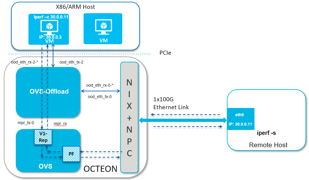
1.6.1. Wire-VM Communication#
A use case where VMs communicate across different hosts.
Setting up the host machine and launching the VM - it is a common step across various types of traffic.
Assign an IP to the host SDP PF internface
# ifconfig <pf-iface> <ip addr>
Ex.
# ifconfig enp1s0f0 30.0.0.3
1.6.1.1. Plain Traffic#
Setup Detail
Launching OVS as per use case
Steps to create bridge and attach ports
Setting up bridge and attaching ports
Setting up the peer machine
Peer machine can be another host machine which is connected to the octeon board over ethernet link.
Assign IP to one of the host’s netdev which is connected to octeon board
# ifconfig <eth-iface> <ip addr>
Ex.
# ifconfig eth0 30.0.0.11
Launching dao-ovs-offload
Ping from host interface to peer machine or vice versa
# ping 30.0.0.11
PING 20.11 (30.0.0.11) 56(84) bytes of data.
64 bytes from 30.0.0.11: icmp_seq=1 ttl=64 time=0.367 ms
64 bytes from 30.0.0.11: icmp_seq=2 ttl=64 time=0.217 ms
64 bytes from 30.0.0.11: icmp_seq=3 ttl=64 time=0.186 ms
64 bytes from 30.0.0.11: icmp_seq=4 ttl=64 time=0.237 ms
64 bytes from 30.0.0.11: icmp_seq=5 ttl=64 time=0.132 ms
Running Demo
1.6.1.2. VLAN Traffic#
Setup Detail

Launching OVS as per use case
Steps to create bridge and attach ports
Setting up bridge and attaching ports
Configuring VLAN
Setting up the peer machine
Create VLAN interface on the peer machine to send packets with tag 100
# ip link add link <eth-iface> name <vlan-iface> type vlan id 100
# ifconfig <vlan-iface> <ip addr>
Ex.
# ip link add link eth0 name eth0.100 type vlan id 100
# ifconfig eth0 30.0.0.11
Delete the VLAN interface
# ip link delete <vlan-iface>
Ex.
# ip link delete eth0.100
Launching dao-ovs-offload
Ping from host interface to peer machine or vice versa
# ping 30.0.0.11
PING 20.11 (30.0.0.11) 56(84) bytes of data.
64 bytes from 30.0.0.11: icmp_seq=1 ttl=64 time=0.367 ms
64 bytes from 30.0.0.11: icmp_seq=2 ttl=64 time=0.217 ms
64 bytes from 30.0.0.11: icmp_seq=3 ttl=64 time=0.186 ms
64 bytes from 30.0.0.11: icmp_seq=4 ttl=64 time=0.237 ms
64 bytes from 30.0.0.11: icmp_seq=5 ttl=64 time=0.132 ms
Running Demo
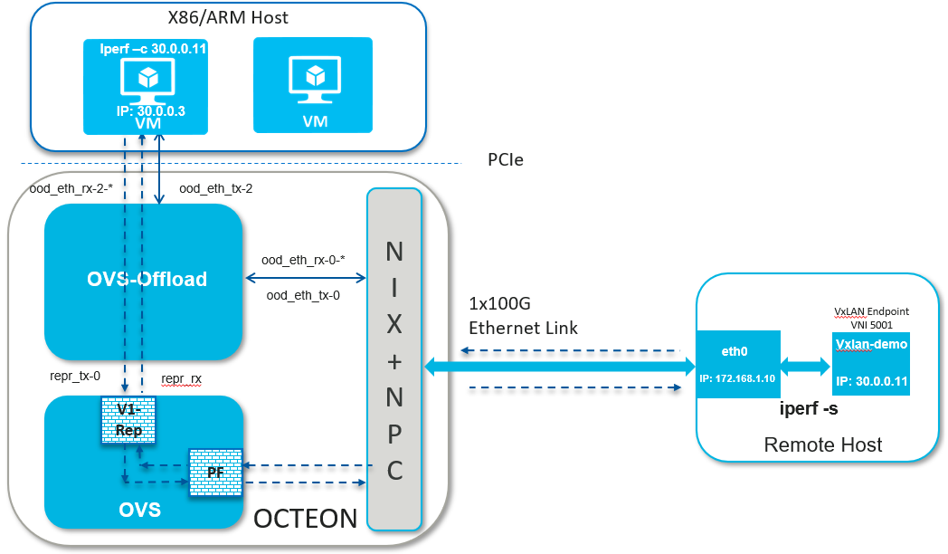
1.6.1.3. VxLAN Traffic#
Setup Detail
Launching OVS as per use case
Steps to create bridge and attach ports
Setting up bridge and attaching ports
Configuring VxLAN
Setting up the peer machine
Create VxLAN endpoint on the peer machine to send packets with VNI 5001
# ip link add <vxlan-intf> type vxlan id <vni> remote <remote-ip> local <local-ip> dev <eth-iface> dstport 4789
# ifconfig <eth-iface> <ip addr>
# ifconfig <vxlan-intf> <ip addr>
Ex.
# ip link add vxlan-demo type vxlan id 5001 remote 172.168.1.20 local 172.168.1.10 dev eth0 dstport 4789
# ifconfig eth0 172.168.1.10/24 up
# ifconfig vxlan-demo 30.0.0.11/24 up
Delete the VxLAN interface
# ip link delete <vxlan-intf>
Ex.
# ip link delete vxlan-demo
Launching dao-ovs-offload
Ping from host interface to peer machine or vice versa
# ping 30.0.0.11
PING 20.11 (30.0.0.11) 56(84) bytes of data.
64 bytes from 30.0.0.11: icmp_seq=1 ttl=64 time=0.367 ms
64 bytes from 30.0.0.11: icmp_seq=2 ttl=64 time=0.217 ms
64 bytes from 30.0.0.11: icmp_seq=3 ttl=64 time=0.186 ms
64 bytes from 30.0.0.11: icmp_seq=4 ttl=64 time=0.237 ms
64 bytes from 30.0.0.11: icmp_seq=5 ttl=64 time=0.132 ms